The circuitry for the electronic mural I made in the first two weeks of January (final product post here) was simple. I used three types of circuit stickers: an LED sticker, a sound sensor sticker, and a micro-controller sticker. Each sticker had the required components embedded, such that I just needed to connect everything. The challenge of the mural was not in the circuit design or control logic (the most complicated of which was charlieplexing) but in the materials and the craft of using those materials.
 Pencil skeleton of the mural.
Originally I had planned to use an Electroninks circuit scribe pen to make the connections. I had used it on paper and it worked like a charm, plus it would easily wash off the wall if I made mistakes, PLUS they had kindly given me a couple pens to test for free. Unfortunately, while once on the wall it worked well, it was a huge hassle to get onto the bumpy surface of the drywall. I had to go over the same line again and again and again, trying to get the ink to grab onto the wall.
Close up of control logic connected using a circuit scribe pen.
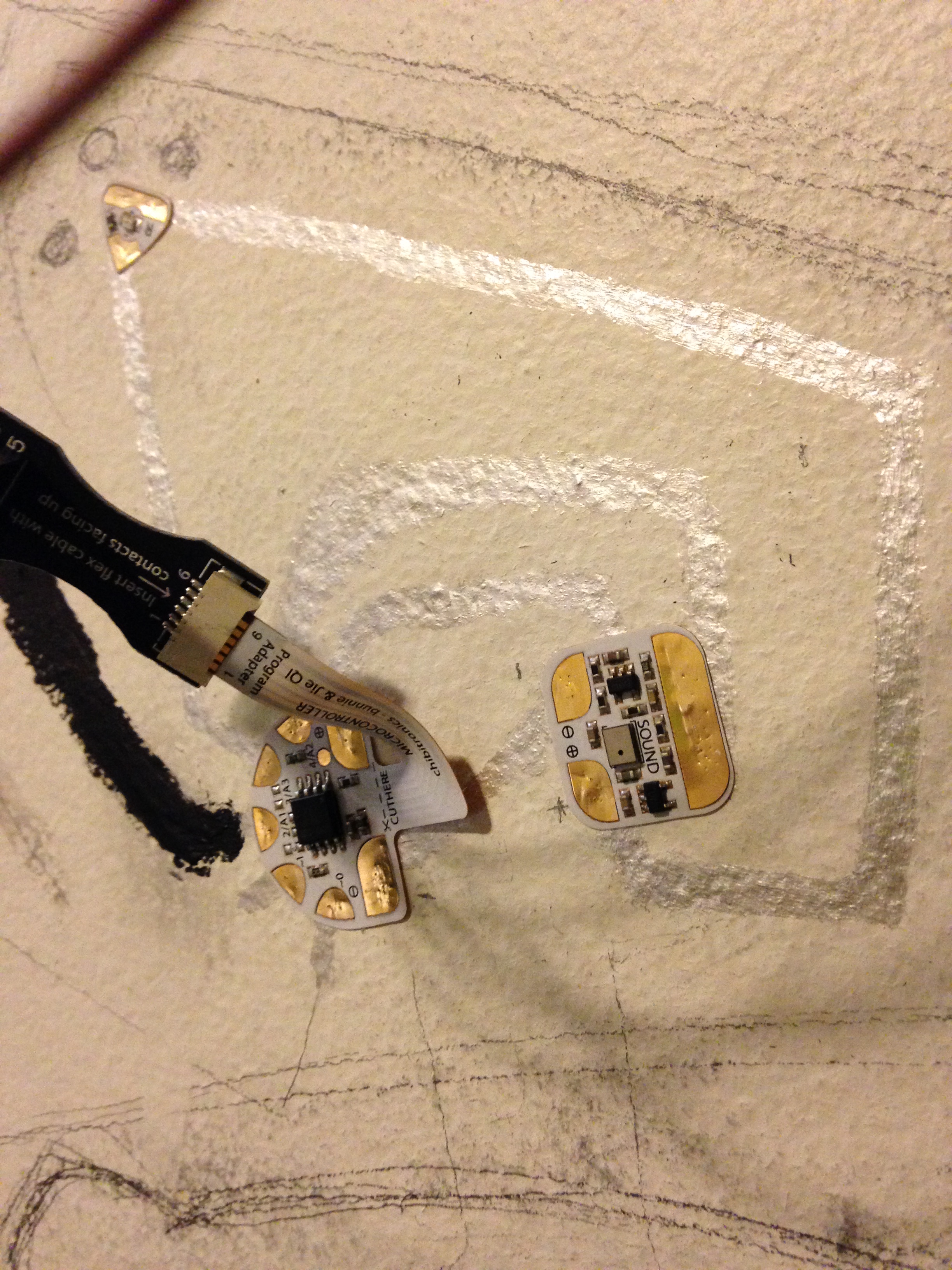
Wide view of the control circuitry, including the multimeter I taped to the wall to facilitate debugging.
Before I move onto the Bare Conductive paint, I should mention that the resistance of the silver ink lines was high, in the thousands of Ohms. This was fine, and in fact all of the control circuitry worked with the silver ink connections, however the lines to power the LEDs would be much longer. Flat surfaces of conductive material vary in resistance according to their aspect ratio, unlike wires, so in order to decrease the resistance of the longer lines I would need to make them wider. This added incentive to abandoning the silver ink, which took forever to apply even as skinny lines.
So I dived deep into Bare Conductive paint. The two conductive products would not connect with each other, so I had to redo any lines that I had failed to finish with the pen. I left the control circuitry as silver ink, since it was working and I didn’t want to disturb it, and started on the lines for the LEDs. I made them thick, with room for making them thicker if needed, and the resistance remained in the low thousands of Ohms. I also painted on power lines, naively not worrying about how the resistance of those lines would affect the circuit in a much larger way.
 Of course the power lines had too much resistance to power the circuit. Up until then I had been powering the circuit through the Arduino I was using to program the microcontroller. Powering it using leads connected to the black lines near the outlet did not work at all. I knew I had to bring the power closer with actual wire leads, but I wasn’t sure how best to do this without disturbing the concept of the mural. I had placed the control circuitry where it was thinking that it was near the holes that opened onto the microphone on the real lilypad. (The concept is based on the baby monitor my company makes.) Now I was thinking it made more sense to move it closer to the power plug, which was an upsetting prospect because it meant I would be starting nearly from scratch.
There was another issue. The LEDs weren’t behaving correctly. One LED routinely turned on when its positive terminal was set as an input, which should behave as an open and result in the LED remaining off. (See Wikipedia on charlieplexing for an explanation of why this works.) This disturbed the visual of the LEDs lighting up in order and in turn, since it turned on when another LED was on and, consequentially, out of order.
There were these two issues, plus I hadn’t even begun to paint over the big black lines, which were never part of the visual. While I was tackling the two problems above, I didn’t even realize that this, the painting, would also turn into a huge issue. Stay tuned for starting almost from scratch and delving into the world and paint and water and mixing.

One thought on “Electronic Mural: Part I”